
2.1 Introduction
Pipelining is an implementation technique in which multiple instructions are overlapped in execution, much like an assembly line. It is the key to make processors fast. In pipeline architecture a single task is divided in various stages. Pipelining doesn’t help latency of single task, it helps throughput of the entire workload. Here multiple tasks operate simultaneously using different resources. In pipelining the number of stages accounts for the potential speed of the processor. In this part I have designed a three stage pipeline. This part is further divided into 5 sections. Section 2.2 describes the design of the three stage pipeline. Section 2.3 describes the implementation of the three stage design using HASE simulator. Section 2.4 describes the simulation of the working of the design in the HASE simulator. The subsequent section is used to analyse and conclude on the design.
2.2 Design of the three stage pipeline
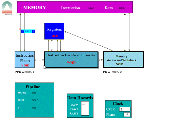
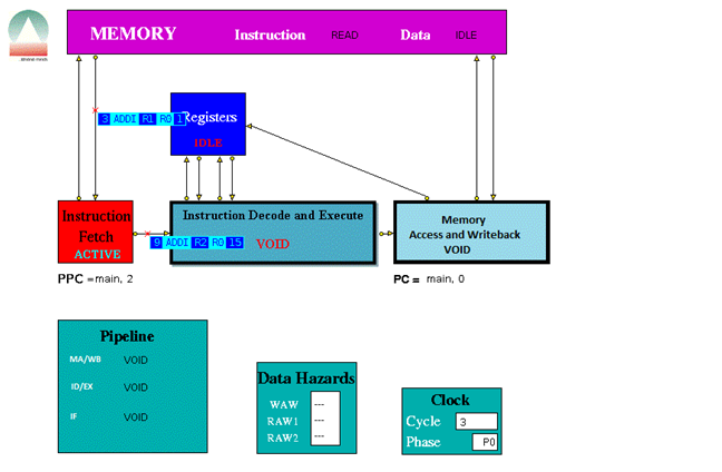
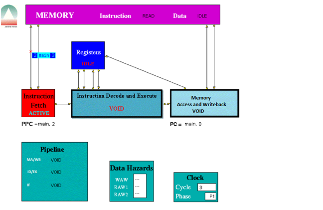
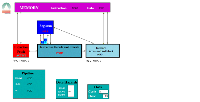
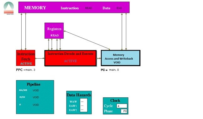
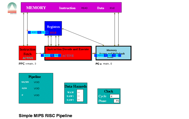
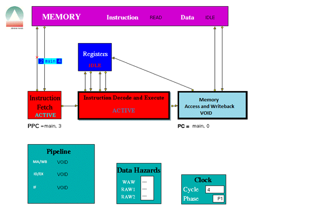
This design is a simple three stage pipeline architecture, which implements a basic MIPS32 architecture. Building a three stage pipeline necessitated combining Instruction decode and Instruction Execute stages as well as the Memory Access and Write Back stages. See figure 2.2. The Instruction decode and Execute Unit is used for decoding and also for both data and address arithmetic, so load/store instructions are processed by this Unit before being sent to the Memory Access and Write back Unit and then to Memory. The Instruction decode and Execute Unit also executes the additions required for integer test and relative branch instructions, so the Memory Access and Write back Unit also executes branches.
The Instruction-decode and Execute Unit receives its operands from the Instruction Decode Unit, which is closely coupled to the Registers. These consist of 32 Integer Registers. The results from both arithmetic/logic and load instructions are returned to the Registers by the Memory Access and Write Back Unit.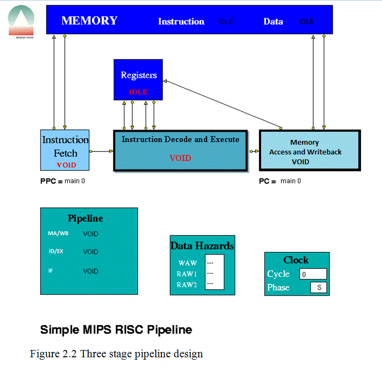
Here the MIPS instruction set was used. The instruction sets are in the Appendix A
2.2.a.
Data Hazards
Data Hazards occur when an instruction requires the result of a previously issued but as yet uncompleted instruction. Hazards are displayed by a separate Data Hazards entity in the HASE model. See figure 2.2.a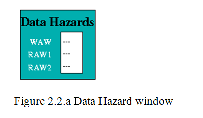
Pipeline Units
Instruction Fetch
The Instruction Fetch Unit accesses the Memory for instructions using the address in a Pre-fetch Program Counter (PPC). PPC is initially set equal to 0 (as is the PC register in the Memory Access Unit). Send the content of program count (PC) to memory and fetch the current instruction from memory to update the PC.
Instruction Decode and Execute
The Instruction Decode Unit receives instruction packets from the Instruction Fetch Unit and the result of the arithmetic/logic instruction is computed using native-mode operations of the simulation execution platform. This unit then sends instruction/operand packets to the Memory Access and Write back Unit. Before accessing operands from the Registers, it checks for data hazards. If a hazard is detected, the Unit enters the Held state and the instruction remains in the Instruction Decode Unit until the next clock, when the checks are repeated.
Memory Access and Write back
The Memory Access Unit receives instruction packets from the Instruction decode and execute unit. Each packet contains two data fields in addition to the instruction and status fields. Arithmetic instruction packets contain the data to be sent to the registers in the data1 field. Load instruction packets contain a memory address in the data1 field which is sent to the Memory Unit. The data returned from the Memory is passed to this Unit. Store instruction packets contain a memory address in the data1 field and the data to be sent to Memory in the data2 field. Branch instruction packets contain the new PC address or the offset in the instruction field of the packet. Conditions are evaluated in the relevant Execution Unit and carried through as bits in the Status field of the packet. When the appropriate change has been made to the Program Counter, an untraced packet is sent to the Instruction Fetch Unit to unlock the Held condition in that Unit and to update the Pre-fetch Program Counter. Whenever a valid packet is received, this Unit also constructs a Register Write Request packet and sends it to the Registers. The Registers have three ports, two for reading and one for writing. The Registers unit is not clocked and acts immediately on each packet it receives. To ensure that the simulation works correctly, there is a short delay in the Instruction Decode and Execution unit before it performs the WAW/RAW checks or reads the register values, i.e. a value being written in one clock cycle can also be read in that clock cycle.
Memory and Registers
The Memory
The Memory contains two arrays, one for instructions and one for data. These are held separately because instructions are held in readable (string) form for visualisation purposes whilst data values are held as integers. Each word in both memories contains its own byte address as well as its instruction or data. The Memory receives instruction requests from the Instruction Fetch Unit and Read/Write requests from the Memory Access Unit and, as appropriate, either returns the contents of the requested memory word to the requesting unit or updates it. It checks for invalid addresses, and sets an error flag in the Scoreboard if either occurs.
The Registers
Each word in the Main Registers array contains an index number field, a data field and a ‘Busy Bit’ field. All the data and Busy Bit values are initially set to zero. Main Register 00 is read-only, i.e. writing to it has no effect.
2.3 Implementation in HASE
To implement the above design in HASE simulator, I first created various .gif files using Microsoft Paint tool, to be used in the HASE simulator. Then I have written the EDL file and named it as 3StagePLA.edl.
Entity Definition File
EDL is the entity definition file and it describes the components of the architecture, their ports and parameters, the links between them and the hierarchical structure (in essence the logical structure of the experiment).
The EDL file starts with the PREAMBLE section of the project definition specifies the basic attributes of the project, for example its name, working directory and author.
PROJECT (
PREAMBLE (
NAME “3StagePLA”
AUTHOR “Anshuman Biswal”
VERSION 1
DESCRIPTION “3 Stage pipeline based on MIPS32 (simplified instruction set)”
)
Then the PARAMLIB section was defined which contains type definitions of parameters used by the project. It contains the definition of the error description word array, instruction structures, instruction set,
— Definition of instruction set
INSTR (t_mips_instrn_set, [(VOID),
(LOAD(LB,LBU,LH,LHU,LW,LWL,LWR), RSTRUCT (t_load, load_field)),
(STORE(SB,SH,SW,SWL,SWR), RSTRUCT (t_store, store_field)),
(ALU(ADD,ADDU,SUB,SUBU,AND,OR,XOR,NOR,SLLV,SRLV,SRAV,SLT,SLTU), RSTRUCT (t_alu, alu_field)),
(ALUI(ADDI,ADDIU,ANDI,ORI,XORI,SLTI,SLTIU,SLL,SRL,SRA), RSTRUCT (t_alui, alui_field)),
(LUI, RSTRUCT(t_loadi, loadi_field)),
(BRNC(BEQ,BNE), RSTRUCT (t_brnc, brnc_field)),
(BRNCI(BLEZ,BGTZ,BLTZ,BGEZ), RSTRUCT (t_brnc_i, brnc_i_field)),
(J, RSTRING (label, “-“)),
(JR, RSTRING (src_reg, “-“)),
(NOP),(BREAK)
], function);
Instruction register/packet, instruction memory array data memory word, data memory array, data memory access packet, links connecting memory, pipeline stages, registers, etc.
— definition of links connecting to memory
LINK(l_mem,[ (MEM_ACCESS_I,RSTRUCT(t_i_mem_access,DP)),
(MEM_ACCESS_D,RSTRUCT(t_d_mem_access,DP)),
(MEM_INSTR,RSTRUCT(t_instrn_reg,DP)),
(MEM_DATA,RSTRUCT(t_exe_rslt,DP))]);
— definition of links connecting pipeline stages
LINK(l_pipe,[ (INSTRUCTION,RSTRUCT(t_instrn_reg,DP)),
(UNIT_DATA,RSTRUCT(unit_data_struct,DP)),
(WRITE_BACK,RSTRUCT(t_write_back_struct,DP)),
(BRANCH_RESULT,RSTRUCT(t_branch_rslt,DP))]);
)
After the PARAMLIB section GLOBALS section is defined and it contains definitions of parameters that are accessible to all of the entities in the project
GLOBALS(
RINT(branches_taken, 0);
RINT(branches_not_taken, 0);
RINT(memory_reads, 0);
RINT(memory_writes, 0);
RINT(instructions_issued, 0);
RRANGE (log_max_cycles, 1, 20, 10)
)
The next definition in the EDL file is the ENTITYLIB which enables the user to create a library of entities, the basic components from which architecture can be created. This section is similar to the parameter library in that it creates definitions of entities which are used later in the STRUCTURE section to create the architecture.
ENTITYLIB (
ABSTRACT Biclocked sync ( )
ENTITY Clock sync ( )
ENTITY Clockphase sync ( )
ENTITY registers (
DESCRIPTION (“MIPS Registers”)
STATES (RF_IDLE, RF_WRITE, RF_READ)
PARAMS (
RARRAY ( prog_reg_set, main_reg, 32);
)
PORTS (
PORT(from_instr_decode1,l_reg,DESTINATION);
PORT(to_instr_decode1,l_reg,SOURCE);
PORT(from_instr_decode2,l_reg,DESTINATION);
PORT(to_instr_decode2,l_reg,SOURCE);
PORT(from_write_back,l_reg,DESTINATION);
)
);
The next section is the STRUCTURE section of the project definition and it describes which entities from the entity library are to be included in the architecture description and how many of them there are. It also deals with how the entities and connected together.
- architecture_entity – This defines a component (AENTITY) to be included in the architecture.
STRUCTURE(
— List of entity instances in top-level model
AENTITY memory MEMORY (
DESCRIPTION(“memory”)
);
AENTITY registers REGISTERS (
DESCRIPTION(
);
AENTITY instr_fetch INSTR_FETCH (
DESCRIPTION(“Instruction Fetch”)
);
.
.
.
AENTITY Clock CLOCK ( DESCRIPTION (“Clock”));
AENTITY Clockphase CPHASE (DESCRIPTION (“Clock display”));
- communication_channel – This defines a link (CLINK) that interconnects AENTITIES in the architecture.
CLINK(instr_fetch.INSTR_FETCH[to_memory]->memory.MEMORY[instr_request],1);
CLINK(memory.MEMORY[instr_out]->instr_fetch.INSTR_FETCH[from_memory],1);
CLINK(mem_access.MEM_ACCESS[to_memory]->memory.MEMORY[data_request],1);
CLINK(memory.MEMORY[data_out]->mem_access.MEM_ACCESS[from_memory],1);
CLINK(instr_fetch.INSTR_FETCH[instr_out]->instr_decode.INSTR_DECODE[instr_in],1);
CLINK(instr_decode.INSTR_DECODE[to_registers1]->registers.REGISTERS[from_instr_decode1],1);
CLINK(registers.REGISTERS[to_instr_decode1]->instr_decode.INSTR_DECODE[from_registers1],1);
CLINK(instr_decode.INSTR_DECODE[to_registers2]->registers.REGISTERS[from_instr_decode2],1);
CLINK(registers.REGISTERS[to_instr_decode2]->instr_decode.INSTR_DECODE[from_registers2],1);
Entity Layout File
First I have written the .edl file and then I wrote the .elf file to put the various gif files that I have created in respective position of the design and named it as 3StagePLA.elf. This file contains information related to an entity (position, states, ports and parameters) and to a link (link corner positions) when displayed on screen. An Entity Layout File contains a list of lines each of which should have one of the following formats:
- object_id : POSITION (x,y) info1 info2 info3
- object_id : STATES state1_name gif_image1 state2_name gif_image2 …
- object_id : PORT port_name SIDE entity_side POSITION port_position position_string ICON icon_file
“registers”);
- object_id : PARAM param_name MODE mode_name POSITION (param_x,param_y)
- object_id :
- object_id : LINKCORNER src_entity src_port dest_entity dest_port no_of_corners (cx1,cy1) …
- bottomcorner : position (x,y)
Where object_id can be either an entity name (which has been declared in the entity library) or a component name defined as a CHILD of a COMPENTITY or as an AENTITY STRUCTURE.
msrsas : position (10,30)
title_v2 : position (70,620)
SCOREBOARD : position (310,455)
SCOREBOARD : PARAM WAW MODE VALUE POSITION (69,42)
SCOREBOARD : PARAM RAW1 MODE VALUE POSITION (69,61)
SCOREBOARD : PARAM RAW2 MODE VALUE POSITION (69,80)
PIPE_DISP : position (70,404)
PIPE_DISP : PARAM M_A MODE VALUE POSITION (80,40)
PIPE_DISP : PARAM I_D MODE VALUE POSITION (80,73)
PIPE_DISP : PARAM I_F MODE VALUE POSITION (80,109)
Coding Entity Behaviour
For each entity, an entity.hase file is created containing Hase++ program code that defines its behaviour. It includes a set of library routines to provide for process oriented discrete event simulation and a run time system for multi-threading many entities in parallel and keeping track of simulation time.
Instruction-Fetch Entity Behaviour
I wrote the instruction fetch entity behaviour in instr_fetch.hase file. The hase file starts with a declaration section ($class_decls) containing declarations of entity references, structures, variables and classes.
$class_decls
sim_entity_id pipe;
scoreboard * mySB;
instr_decode * myID;
mem_access * myMA;
//structures and variables
t_i_mem_access InstrMemRequest;
t_instrn_reg IF_Input_Reg, InputPacket, IF_Output;
t_mips_instrn_set Instruction;
t_branch_rslt BranchResult;
bool Hold;
bool Branch, DelaySlot, Jump;
bool ClearValid, SetClearValid;
int ClockPhase;
pc_struct next_PPC, old_PPC;
bool PPC_init, SetPPC_init; // used to ensure that no instruction accesses
// occur until PPC has been set from PC
int branch_address;
int branch_status;
int MemReqOutstanding;
int NewSequence; // = 8 if instruction fetch is the start of new sequence
int old_state;
//classes
void InitialisePC(pc_struct PC);
void ClearPipe();
and a section for definitions of declared classes is present under $class_defs.
$class_defs
void instr_fetch::InitialisePC(pc_struct PC)
// Invoked by Memory Access during initialisation
// Updates PPC with new value of PC
{
strcpy(next_PPC.label, PC.label);
next_PPC.offset = PC.offset;
SetPPC_init = true;
}
void instr_fetch::ClearPipe() // invoked by MA at a branch
{
SetClearValid = true; // sets ClearValid in ClockPhase 1; ClearValid is
// reset by first instruction of a new sequence
}
The $pre section contains code to be executed before the simulation proper starts, e.g. initialisation of variables (all variables, classes, ) and the setting of pointers to other entities.
$pre
pipe = sim.get_entity_id(“PIPE_DISP”);
m_access = sim.get_entity_id(“MEM_ACCESS”);
myID = (instr_decode*)sim.get_entity(sim.get_entity_id(“INSTR_DECODE”));
myMA = (mem_access*)sim.get_entity(m_access);
SetPPC_init = false;
PPC_init = false;
sim_entity_id m_access;
old_PPC.offset = 0;
MemReqOutstanding = 0;
Branch = false;
DelaySlot = false;
ClearValid = true; // initially set, awaiting initialisation of PPC by MA Unit
SetClearValid = true;
NewSequence = 0; // = 8 if instruction fetch is to start of new sequence
Hold = false;
IF_Input_Reg.status = 0;
IF_Output.status = 0;
IF_Output.instrn.reset();
my_state = IF_VOID;
old_state = IF_VOID;
dump_state();
Since this is a two-phase clocked system, the definition of each clocked entity will include the following: EXTENDS (Bi-clocked), where “Bi-clocked” is an abstract entity which registers the entity to be clocked with the appropriate pre-defined clock entity. This clock sends phase 0 and phase 1 clock signals to the clocked entities and receives “done” signals back from them once they have completed their actions in each phase. The statements $phase0 and $phase1 in the entity’s .hase file act as include statements for the code in the “clocked” entity which interacts with the clock entity. In phase 0 an entity typically tests for the presence of an input packet from another entity, reads an input packet (SIM_CAST (packet_type, InputPacket, ev);) and carries out its internal actions in response. In the case of a processor pipeline unit, for example, this will involve decoding the instruction in some way, using classes in the global functions files. The global function files global_fns.h and global_fns.c are accessible from all entities. In phase 1, entities normally send packets to their successor units ready to be read at the next phase 0 clock signal.
In phase 0 of the hase file the pre program counter (PPC) normal update is done.
strcpy(PPC.label, next_PPC.label);
PPC.offset = next_PPC.offset;
If there’s an update from the MA (Memory Access) unit then again the PPC update is done. To read the packets from the MA unit sim_waiting() is used. This method computes the number of events (from within the queue of events that are waiting to be processed) that are for the entity containing the sim_waiting statement and that match the predicate requirements. It is normally used in clocked entities to look for packets sent by some other entity in the previous clock period. So here we look for the packets sent by the MA unit
if (sim_waiting(pc_packet) > 0)
{
sim_select (pc_packet, ev);
SIM_CAST( t_branch_rslt, BranchResult, ev);
branch_address = BranchResult.branch; // not used yet
branch_status = BranchResult.status;
strcpy(PPC.label, BranchResult.addr.label);
PPC.offset = BranchResult.addr.offset;
strcpy(next_PPC.label, PPC.label);
next_PPC.offset = PPC.offset; // to ensure that PPC remains
// = target address if there’s a Hold
MemReqOutstanding = 0; // all further replies will be ignored
NewSequence = 8;
Branch = false;
}
Then check if the Instruction fetch is not held by the branch or external condition.
if (!Hold)
Check for reply from memory and copy packet received into input register. Memory access time may be >1 clock. At a pipeline clear, ClearValid flag is set which says all instructions are invalid until one is returned with bit 28 set indicating first of new sequence. This bit is set with first request to memory after a clear and resets ClearValid flag when it returns.
IF_Input_Reg.status = 0; // initialise to non-valid
if (sim_waiting(mem_packet) > 0)
{
sim_select(mem_packet, ev);
SIM_CAST(t_instrn_reg, InputPacket, ev);
IF_Input_Reg.instrn = InputPacket.instrn;
IF_Input_Reg.status = InputPacket.status & -3;
// remove access type bit
if ((IF_Input_Reg.status & 9) == 9) // bits 31 and 28 = 1
{ClearValid = false;}
if (!ClearValid)
{MemReqOutstanding –;} // decrement memory requests outstanding
} // end of packet from memory
if (ClearValid)
{IF_Input_Reg.status = 0;}
if ( (IF_Input_Reg.status & 1) == 1 ) // valid instruction
sim_select method is used when an entity can have received packets on a number of ports since it processed the last one, sim_select is used in conjunction with sim_waiting to select the appropriate packet for a particular action.Here it is used to receive the packets from the memory. To extract the packet SIM_CAST is used. If it is a valid instruction then Decode input registers content to look for branches.
if ( (IF_Input_Reg.status & 1) == 1 ) // valid instruction
// Decode input register content to look for branches
{
if ( IF_Input_Reg.instrn.function == t_mips_instrn_set::J
|| (IF_Input_Reg.instrn.function == t_mips_instrn_set::JR)
|| IF_Input_Reg.instrn.decode_BRNC()
|| IF_Input_Reg.instrn.decode_BRNCI()
//|| IF_Input_Reg.instrn.decode_BFP()
)
Set Branch, this sets Delay Slot in ClockPhase 1 so that the next instruction, in the delay slot, won’t increment PC and then Decode absolute jumps to stop pre-fetching.
{Branch = true;}
if ( IF_Input_Reg.instrn.function == t_mips_instrn_set::J
|| (IF_Input_Reg.instrn.function == t_mips_instrn_set::JR)
|| (IF_Input_Reg.instrn.function == t_mips_instrn_set::BREAK) )
{Jump = true;}
} // end of if valid instruction
if the instruction issued is a valid instruction, and it is not a ‘filler’ instruction (i.e. NOP / VOID), increment the global fn.
if( IF_Input_Reg.instrn.function == t_mips_instrn_set::J
|| IF_Input_Reg.instrn.decode_LOAD()
|| IF_Input_Reg.instrn.decode_STORE()
|| IF_Input_Reg.instrn.decode_ALU()
|| IF_Input_Reg.instrn.decode_ALUI()
|| IF_Input_Reg.instrn.decode_BRNC()
|| IF_Input_Reg.instrn.decode_BRNCI()
|| (IF_Input_Reg.instrn.function == t_mips_instrn_set::JR)
)
{instructions_issued++;}
If PPC has been initialised from PC and if there are none or one memory requests outstanding, access memory for next instruction and increment Pre-fetch Program Counter
if ((MemReqOutstanding <= 1) && PPC_init && (!Jump))
{
InstrMemRequest.status = 2 | NewSequence;
strcpy(InstrMemRequest.addr.label, PPC.label);
InstrMemRequest.addr.offset = PPC.offset ;
send_MEM_ACCESS_I(to_memory, InstrMemRequest);
NewSequence = 0;
MemReqOutstanding ++; // increment memory requests outstanding
next_PPC.offset = PPC.offset + 1; // was + 4
strcpy(next_PPC.label, PPC.label);}} // end of if IF not held up
and then set the state.
if ((IF_Input_Reg.status & 1) == 0)
{my_state = IF_VOID;}
if (((IF_Input_Reg.status & 1) == 1) && !Hold)
{my_state = IF_BUSY;}
if (((IF_Input_Reg.status & 1) == 1) && Hold)
{my_state = IF_HELD;}
if (old_state != my_state || old_PPC.offset != PPC.offset) {
dump_state(); old_state = my_state; old_PPC.offset = PPC.offset;
}
After setting the state send the packet to the pipe_disp using sim_schedule method. This method schedules an event to an entity; it does not cause an entry to be made in the trace file. sim_schedule is normally used in conjunction with SIM_PUT. To assemble the output copy the input register into output packet.
IF_Output.instrn = IF_Input_Reg.instrn;
IF_Output.status = IF_Input_Reg.status;
In phase 1 of the clock cycle send the outputs to the Instruction-decode and execute stage.
if (!Hold || (ClearValid && !myID->DelaySlot))
{
if (DelaySlot)
{IF_Output.status = IF_Output.status | 4;
Branch = false;}
if ((IF_Output.status & 1) == 1)
{send_INSTRUCTION(instr_out, IF_Output);}
else
{sim_schedule(instr_out, 0.0, INSTRUCTION,
SIM_PUT(t_instrn_reg, IF_Output));}
Instruction decode and execute entity behaviour
I wrote the instruction decode and execute entity behaviour in instr_decode.hase file. This file also contains the $class_decls , $class_defs and $pre section.In phase 0 of the clock cycle in the decode and execute phase I deal with the input packets that was sent from the Instruction Fetch stage. Check If IDHold or Hazard is set, then no packet will have been sent to this unit and no packets must be sent to MA units. If ID Hold is set, current instruction must not be processed.
if ((!Hazard && !Hold && !SecondCycle) || ClearValid)
{
ID_Input_Reg.status = 0; // initialise to nonvalid
if (sim_waiting(ev, instr_packet) > 0)
{
SIM_CAST( t_instrn_reg, InputPacket, ev );
ID_Input_Reg.status = InputPacket.status;
ID_Input_Reg.instrn = InputPacket.instrn;
}
if ((ID_Input_Reg.status & 5) == 5)
{DelaySlot = true;}
At a pipeline clear, ClearValid flag is set which says all instructions must be set invalid until one arrives with bit 28 set indicating first of new sequence. This bit resets ClearValid.
if ((ID_Input_Reg.status & 9) == 9) // bits 31 and 28 = 1
{ClearValid = false;}
} // end of Hold, etc
if (ClearValid)
{ID_Input_Reg.status = 0;}
Send the packet to the pipeline display ,set the state.
sim_hold(1); // to allow write by Write Back unit
sim_schedule(pipe, 0.0, INSTRUCTION,
SIM_PUT(t_instrn_reg, ID_Input_Reg));
if ((ID_Input_Reg.status & 1) == 0)
{my_state = ID_VOID;}
if (((ID_Input_Reg.status & 1) == 1) && !Hold)
{my_state = ID_BUSY;}
if (((ID_Input_Reg.status & 1) == 1) && Hold)
{my_state = ID_HELD;}
Check for the data hazards and then check for the structural and control hazards to check whether the instructions can be executed or not.
temp_buff1.instrn = ID_Input_Reg.instrn;
if (Hazard)
{temp_buff1.status = 0;}
else
{temp_buff1.status = ID_Input_Reg.status;}
Checkhaz = mySB->CheckHazards(temp_buff1);
Then update the scoreboard display and if valid instruction and hazard, set my_state = Held. And If valid instruction and no hazards, assemble output and assemble the operands
if (((ID_Input_Reg.status & 1) == 1) && (!Hazard) && (!Hold))
{
// assemble operands
if (source_regs == 0)
{
ID_Output.data1 = 0; // set data1 = 0
ID_Output.data2 = 0; // set data2 = 0
// for instructions which have no reg sources
}
if (source_regs >= 1)
{
if (src1T == ‘R’) {strcpy (read_src1.reg_type, “R”);}
read_src1.reg_no = src1;
send_REG_READ(to_registers1, read_src1);
sim_get_next(ev); //wait for reply
if (ev.from_port(from_registers1))
{SIM_CAST(t_reg_value, src1_value, ev);
ID_Output.data1 = src1_value.value;
ID_Output.data2 = 0;} // set data2 = 0 for instructions
// which only have 1 data value
}
if (source_regs == 2)
{
if (src2T == ‘R’) {strcpy (read_src2.reg_type, “R”);}
read_src2.reg_no = src2;
send_REG_READ(to_registers2, read_src2);
sim_get_next(ev); //wait for reply
// copy src2_value into output packet
if (ev.from_port(from_registers2))
{SIM_CAST(t_reg_value, src2_value, ev);
ID_Output.data2 = src2_value.value;}
}
Copy instruction and status into output register. And if the pipeline is the progress pipeline then move instruction/operand packets through pipeline registers.
Any = 0;
for ( i= (latency-1); i>=1; i–)
{
Pipeline[i].status = Pipeline[i-1].status;
if ((Pipeline[i].status & 1) == 1)
{Any = 1;}
Pipeline[i].instrn = Pipeline[i-1].instrn;
Pipeline[i].data1 = Pipeline[i-1].data1;
Pipeline[i].data2 = Pipeline[i-1].data2;
}
If it contains a valid instruction then compute Result and copy into first Pipeline stage output register (Pipeline [0]) and then send the packet to pipeline display
Instruction.status = ID_Output.status;
Instruction.instrn = ID_Output.instrn;
sim_schedule(pipe, 0.0, INSTRUCTION,
SIM_PUT(t_instrn_reg, Instruction));
if (my_state != old_state)
{dump_state();
old_state = my_state;}
In phase 1 of the clock cycle send the packet to the memory access and write back unit using send_UNIT_DATA
if ((Pipeline[latency-1].status & 1) == 1)
{send_UNIT_DATA(int_instr_out, Pipeline[latency-1], 0.0, 17, 2 );}
else
{sim_schedule(int_instr_out, 0.0, UNIT_DATA,
SIM_PUT(unit_data_struct, Pipeline[latency-1]));}
Memory Access and Write-back entity behaviour
I wrote the instruction decode and execute entity behaviour in mem_access.hase file. This file also contains the $class_decls , $class_defs and $pre section. Unless Memory Access and write back unit is held up waiting for a reply from Memory,check for valid packet from decode/execution units and then copy valid packet to MA_Input_Reg.
if (!MAHeld)
{
MA_Input_Reg.status = 0; // Initialise MA_Input_Reg valid to 0
if (sim_waiting(ev, from_int) > 0)
{
SIM_CAST( unit_data_struct, IntOutput, ev );
if ((IntOutput.status & 1) == 1)
{
MA_Input_Reg.status = IntOutput.status;
MA_Input_Reg.instrn = IntOutput.instrn;
MA_Input_Reg.data1 = IntOutput.data1;
MA_Input_Reg.data2 = IntOutput.data2;
}
}
The complete functionality is done as described in section 2.2 under the Pipe line unit subsection (b). If it is Arithmetic instructions then do the write back action. If it is Load instructions then send Read access to Memory and set waiting flag. If it is Store instructions then send Write access to Memory and set waiting flag and if it is Branch operations then execute. If a control transfer occurs (unconditional jump, or
conditional branch for which the condition is satisfied, with no branch predicted), then the instructions in Instruction Fetch (IF) and Instruction Decode (ID) must be invalidated. IF and ID set the status of their outgoing instructions to 0 in Clock Phase 1. ID invokes clearHazard() in the Scoreboard to clear any hazards.
if (Update_PPC)
{
myIF->ClearPipe();
myID->ClearPipe();
//printf(“MEMORY ACCESS: Clearing pipeline\n”);
}
Now I need to process the reply that i got from the memory unit. If MAHold = 1, look for packet from memory for STORE orders, this is an acknowledgement and for LOAD orders, the packet contains data which must be processed. In clock phase 1 send the output to memory if Forward is set. If the input is valid then construct a packet to send to registers using send_REG_WRITE().
//If Forward = 1, send Output to Write Back Unit
if (((MemoryReadAccess == 1) || (MemoryWriteAccess == 1))
&& (MemReqOutstanding == 0))
{
send_MEM_ACCESS_D(to_memory, MemRequest);
MemReqOutstanding = 1;
}
else
{
if ((WB_Input_Reg.status & 1) == 1)
// if input is valid, construct a packet to send to Registers
{
WB_Output.data = WB_Input_Reg.data;
if (WB_Input_Reg.instrn.decode_LOAD())
{Dest_reg = WB_Input_Reg.instrn.load_field.dest_reg;}
else if (WB_Input_Reg.instrn.decode_ALU())
{Dest_reg = WB_Input_Reg.instrn.alu_field.dest_reg; }
else if (WB_Input_Reg.instrn.function == t_mips_instrn_set::LUI)
{Dest_reg = WB_Input_Reg.instrn.loadi_field.dest_reg;}
else if (WB_Input_Reg.instrn.decode_ALUI())
{Dest_reg = WB_Input_Reg.instrn.alui_field.dest_reg; }
destT = Decode_Register(Dest_reg).type;
dest = Decode_Register(Dest_reg).number + IncRegNo;
if (destT == ‘R’) {strcpy(WB_Output.reg_type, “R”);}
WB_Output.reg_no = dest;
send_REG_WRITE(to_registers, WB_Output);
}
}
If Update_PPC is set then send PC value(s) to Instruction Fetch Unit.
if (Update_PPC && ((MA_Input_Reg.status & 1) == 1))
{
BranchResult.branch = 0;
BranchResult.status = 0;
send_BRANCH_RESULT(to_instr_fetch, BranchResult);
Update_PPC = false;
}
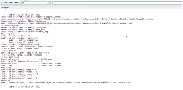
2.4 Simulation using the trace files
To do the simulation using the trace file then the contents files should also be defined. The Memory contains two arrays, one for instructions and one for data. These are held separately because instructions are held in readable (string) form for visualisation purposes whilst data values are held as integers. Each word in both memories contains its own byte address as well as its instruction or data. When a project is loaded, HASE looks for files with the same name as each of the arrays declared in the .edl file, but with a .mem extension and loads the contents into the corresponding array, e.g. the contents of MEMORY.instr_mem.mem are loaded into the instruction memory. Appendix B has the instruction file contents.
And MEMORY.data_mem.mem contains 0 1 2 ….15 .Each number in a new line. The mips_v1.1.params is in Appendix C.
And REGISTERS.main_reg.mem contains 0 0 from 0 to 32 times in a new line as follows.
0 0
0 0
0 0
.
.
.33 times
0 0
After the content files were written, then I built and compiled the project in the HASE simulator
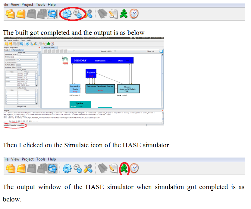
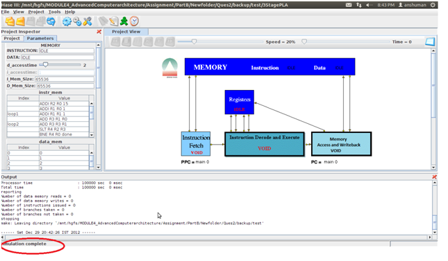
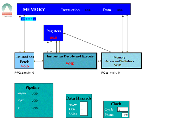
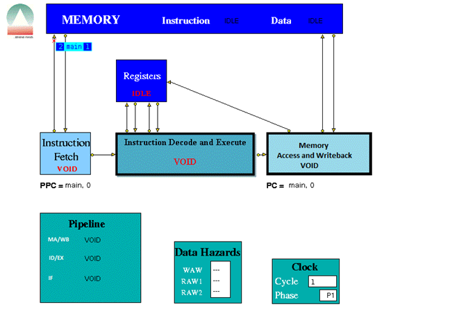
After this step the trace file was generated and was placed in the results folder inside the projects directory with the name 3StagePLA.sim. And trace file was loaded in the HASE simulator as follows

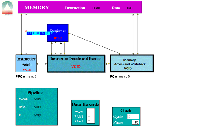
When played the trace file the following were some screen shots of the simulations for the following instructions provided.
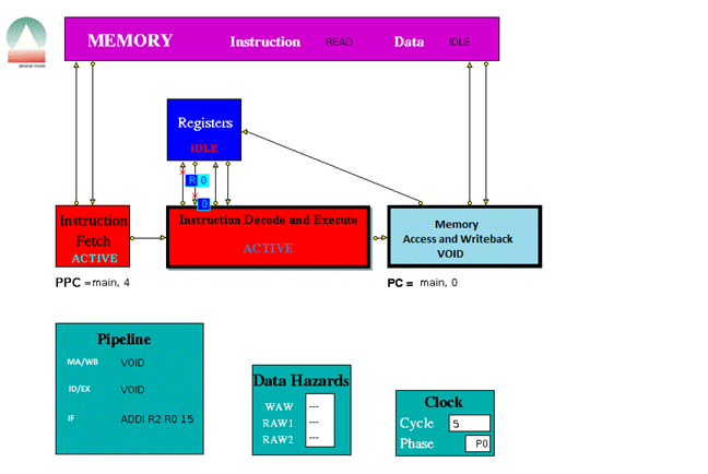
ADDI R2 R0 15 which means R2 = R0 + 15 (=15)
ADDI R1 R0 1 which means R1 = R0 + 1 (=1)
loop1 which means Label (loop1) – does not count as an instruction
ADDI R1 R1 1 which means R1 = R1 + 1 (increment R1 by 1)
ADD R3 R1 R0 which means R3 = R1 + R0 (copy R1 to R3)
loop2 which means Label (loop2) – does not count as an instruction
ADD R3 R3 R1 which means R3 = R3 + R1 (increment R3 by R1)
SLT R4 R2 R3 which means R4 = 1 if R2 < R3 else R4 = 0
BNE R4 R0 done which means Branch to done if R4 != R0 (R4 != 0)
SLL R5 R3 2 which means R5 = R3 Left shifted 2 places
J loop2 which means Branch to loop2
SW R0 0(R5) which means Delay slot: Store R0 at memory location R5
Done which means Label (done) – does not count as an instruction
BNE R1 R2 loop1 which means Branch to loop1 if R1 != R2
NOP which means Delay slot: No operation
BREAK which means End the simulation
NOP which means No operation
The three stage pipeline took 1024 clock cycles to complete all the instructions.
2.5 Simulation analysis
Data Hazards occur when, an instruction requires the result of a previously issued but as yet uncompleted instruction. Here the data hazards was handled using the Data Hazard window. Here the Data hazards are handled through Use bits. Each register has a Use bit which is set when an instruction that will write to the register is issued and reset when the result is written to the register. In the HASE MIPS model the registers are implemented as C++ struct with two fields: Use bit and value.
In the Register Display Window if Register 5 has its Use bit set and has a value of 16, while all the others are in the reset state. Before accessing a source or destination register, the Instruction Decode Unit invokes a class in the Registers entity which reads the relevant Use bit.
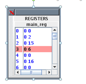
If the Use bit for a Register required as a source operand is set, then there is a RAW hazard, as shown for Register 5 in the Data Hazards Display window.
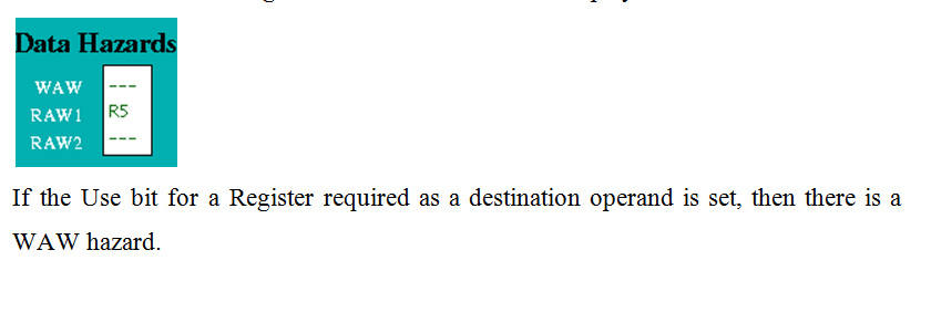
2.6 Conclusion
In this part I have designed a three stage pipeline based on MIPS instruction set. To simulate the design I have used HASE simulator. The three stages are the Instruction fetch as first stage, Instruction decode and Execute as second stage and Memory Access and Write-back as third stage. I have combined the Instruction Decode and Instruction Execute into one unit and combined the Memory Access and Write back into one third stage. From the simulation and by seeing the trace file it is understood that the instructions as mentioned in Appendix B to get completely executed ,took 1024 clock cycles. In PART C we will see how much does the 5 stage pipeline architecture takes to completely execute the same set of MIPS Instructions.
Link to Design and Implementation of 5 Stage Pipeline
References
____________________________________________________________________
[1] Hennessy,J. and Patterson,D. (2005) Computer Organization and Design:T H E H A R D W A R E / S O F T W A R E I N T E R F A C E,3rd edition,Morgan Kaufmann
[2] Hennessy,J. and Patterson,D. (2007) Computer Architecture: A Quantitative Approach, 4th edition, Morgan Kaufmann.
[3] Hesham,E.R. and Mostafa,A.(2005) ADVANCED COMPUTER ARCHITECTURE AND PARALLEL PROCESSING,John Wiley & Sons
[4] Smith,M., Johnson and Horowitz,M.A.(April 1989) “Limits on Multiple Instruction Issue“, Proceedings of the 3rd International Conference on Architectural Support for Programming Languages and Operating Systems.
[5] Princeton wordnet web [Online] Available from http://wordnetweb.princeton.edu/perl/webwn?s=Computer+Architecture&sub=Search+WordNet&o2=&o0=1&o8=1&o1=1&o7=&o5=&o9=&o6=&o3=&o4=&h=
Accesses:31 December 2012
Appendix A MIPS Instruction Sets
____________________________________________________________________
Load/Store Instructions
| Instruction | Description | Example | Result |
| LB | Load Byte | LB R3 1(R0) | Loads Byte from memory location 1 |
| LBU | Load Byte Unsigned | LBU R4 1(R0) | Loads Byte Unsigned from memory location 1 |
| SB | Store Byte | SB R1 1(R0) | Stores Byte in R1 into memory location 1 |
| LH | Load Halfword | LH R4 2(R0) | Loads Halfword from memory location 2 into R4 |
| LHU | Load Halfword Unsigned | LHU R4 2(R0) | Loads Halfword Unsigned from memory location 2 into R4 |
| LUI | Load Upper Immediate | LUI R1 124 | Load 124 in the the upper half of regester R1 |
| SH | Store Halfword | SH R5 6(R0) | Stores Halfword from R5 into memory loction 6 |
| LW | Load Word | LW R4 8(R0) | Loads Word from data memory loaction word 8 into R4 |
| SW | Store Word | SW R3 16(R0) | Stores Word in R3 into location 16 in data memory |
Arithmetic instructions
| Instruction | Description | Example | Result |
| ADDI | Add Immediate Word | ADDI R1 R2 -4 | Store R2 + -4 in R1 |
| ADDIU | Add Immediate Unsigned Word | ADDIU R1 R2 16 | Store R2 + 16 in R1 |
| ADD | Add Word | ADD R1 R2 R3 | Store R2 + R3 in R1 |
| ADDU | Add Word Unsigned | ADD R1 R2 R3 | Store R2 + R3 in R1 |
| SUB | Subtract Word | SUB R1 R2 R3 | Store R2 – R3 in R1 |
| SUBU | Subtract Word Unsigned | SUB R1 R2 R3 | Store R2 – R3 in R1 |
| SLT | Set on less than | SLT R1 R2 R3 | If R2 is less than R3 set R1 to be 1 else set it to 0 |
| SLTI | Set on less than Immediate | SLTI R1 R2 5 | If R2 is less than 5 then set R1 to 1 else set it to 0 |
| SLTU | Set on less than Unsigned | SLTU R1 R2 R3 | If the unsigned value of R2 is less than the unsigned value R3 set R1 to 1 else set it to 0 |
| SLTIU | Set on less than Immediate Unsigned | SLTIU R1 R2 6 | If the R2 is less than 6 (after sign extension)set R1 to 1else set it to 0 |
Logical Instructions
| Instruction | Description | Example | Result |
| AND | And | AND R1 R2 R3 | Stores result of R2 AND R3 into R1 |
| ANDI | And Immediate | ANDI R1 R1 19 | Stores the result of R1 AND 19 back into R1 |
| OR | Or | OR R1 R2 R3 | Stores result of R2 OR R3 into R1 |
| ORI | Or Immediate | ORI R1 R1 128 | Stores the result of R1 OR 128 back into R1 |
| XOR | Exclusive Or | XOR R1 R2 R3 | Stores result of R2 XOR R3 into R1 |
| XORI | Exclusive Or Immediate | XORI R1 R1 64 | Stores the result of R1 OR 64 back into R1 |
| NOR | Nor | NOR R1 R2 R3 | Stores result of R2 NOR R3 into R1 |
| SSL | Shift Word Left Logical | SSL R1 R2 4 | Shift R2 4 bits to the left and store in R1 |
| SRL | Shift Word Right Logical | SRL R1 R2 2 | Shift R2 2 bits to the right and store in R1 |
| SRA | Shift Word Right Arithmetic | SRA R3 R4 2 | Arithmrticaly shift R4 2 bits right and store in R3 |
| SLLV | Shift Word Left Logical Varable | SLLV R1 R2 R3 | Shift R2 left by R3 bits and store in R1 |
| SRLV | Shift Word Right Logical Varable | SRLV R1 R2 R3 | Shift R2 right by R3 bits and store in R1 |
| SRAV | Shift Word Right Arithmetic Varable | SRAV R1 R2 R3 | Shift R2 right arithemeticaly by R3 bits and store in R1 |
Jump Instructions
| Instruction | Description | Example | Result |
| J | Jump | J 8 | Jump to instruction 8 |
| JR | Jump Register | J R1 | Jump to the instruction number held in R1 |
Branch Instructions
| Instruction | Description | Example | Result |
| BEQ | Branch on equal | BEQ R1 R2 4 | Branch forward 4 instructions if R1 and R2 are equal |
| BNE | Branch on not equal | BNE R1 R2 8 | Branch forward 8 instructions if R1 and R2 are not equal |
| BLEZ | Branch on less than or equal to zero | BLEZ R2 -2 | Branch back 2 instructions if R2 is less than or equal to zero |
| BGTZ | Branch on greater than zero | BGTZ R2 -2 | Branch back 2 instructions if R2 is greater than zero |
| BLTZ | Branch on less than zero | BLTZ R2 3 | Branch forward 3 instructions if R2 is less than zero |
| BGEZ | Branch on greater than or equal to zero | BGTZ R2 5 | Branch forward 5 instructions if R2 is greater than or equal to zero |
| BLTZAL | Branch on less than zero and link | BLTZAL R2 3 | Branch forward 3 instructions if R2 is less than zero |
| BGEZAL | Branch on greater than or equal to zero and link | BGTZAL R2 5 | Branch forward 5 instructions if R2 is greater than or equal to zero and link |
Other Instructions
| Instruction | Description | Example | Result |
| BREAK | Breakpoint | BREAK | Halt |
| NOP | No Operation | NOP | No operation |
Appendix B Instructions File (MEMORY.instr_mem.mem)
____________________________________________________________________
ADDI R2 R0 15
ADDI R1 R0 1
loop1:
ADDI R1 R1 1
ADD R3 R1 R0
loop2:
ADD R3 R3 R1
SLT R4 R2 R3
BNE R4 R0 done
SLL R5 R3 2
J loop2
SW R0 0(R5)
done:
BNE R1 R2 loop1
NOP
BREAK
NOP
Appendix C Parameter File (mips_v1.1.params)
____________________________________________________________________
0 (branches_taken)
0 (branches_not_taken)
0 (memory_reads)
0 (memory_writes)
0 (instructions_issued)
10 20 1 (log_max_cycles)
CLOCK (clockName)
IDLE (INSTRUCTION)
IDLE (DATA)
2 8 1 (d_accesstime)
1 (i_accesstime)
65536 (I_Mem_Size)
65536 (D_Mem_Size)
128 (NoOfElements)
64 (NoOfElements)
32 (NoOfElements)
CLOCK (clockName)
main (label)
0 (offset)
CLOCK (clockName)
CLOCK (clockName)
main (label)
0 (offset)
— (WAW)
— (RAW1)
— (RAW2)
0 (cycle)
10.0 (period)
-1.0 (period1)
CLOCK (clockName) 0 (cycle)
