
Home » Tech Talk (Page 5)
Category Archives: Tech Talk
Developing a formal model of a composite web service system
Acknowledgements
Dr. Hariharan Ramasangu of MSRSAS, Bangalore college is highly acknowledged for providing help in solving this assignment.This solution was done as part of solving the assignment of CSN2505 (Applied Formal Methods) module of the course MSc[Engg.] in Computer Science and Networking branch in M S Ramaiah School of Advanced Studies under Coventry University,United Kingdom.
Introduction
In computer science, specifically software engineering and hardware engineering, formal methods are a particular kind of mathematically based techniques for the specification, development and verification of software and hardware systems. Logic is the use and study of valid reasoning and formal logic is the study of inference. At the heart of the formal methods and in fact in all models there lies the equation M ⊨ Ф where M is some sort of situation or model of a system, and φ is a specification, a formula of that logic, expressing what should be true in situation M[9].
As web services are leading to the next generation of electronic commerce, how to ensure design correctness for critical web services has been an important issue. This part of the paper will show how to model a given composite web services and formulate specifications for model checking. Here the modelling is done for a composite web service which is a ticket reservation system comprising of three web services namely airline reservation, vehicle reservation and hotel reservation. The system cannot satisfy a request completely by any single component of the system. Here the Web service behaviours are divided into two types: operational behaviours and control behaviours. The operational behaviour, which is application dependent, illustrates the business logic that underpins the functioning of a Web service. The control behaviour, which is application independent, acts as a controller over the operational behaviour and guides its execution progress.
States and label of operation and control behaviour
Composite Web service behaviour is a 5 tuple W=(S, L, T, s°, F)
where – S = finite set of state names.
– s°ϵ S : initial state.
– F ⊆ S : a set of final states.
– L : a set of transition labels
T ⊆ S x L x S is transition relation.
Each transition t = (Ssrc , L, Sdest ) consist of a source state Ssrc ϵ S , a destionation state Sdest , a transition label l ϵ L
The Control behaviour is the execution progress or the states of the business logic of a web service. The control behaviour relies on number of states like not activated, received, activated, suspended, check processing, commit. The control behaviour of a web service can be expressed as Wco = ( Sco,Lco,Tco,soco, Fco )
The operational behaviour shows the business logic or the functionality of the web service. The operational behavioud of a web service can be expressed as
Wob = (Sob,Lob,Tob,soob , Fob) . The various labels of this web service can be start, invoke, processing, failure, commit, retrial, reply, roll back.
Development of transition rules and state transition diagram
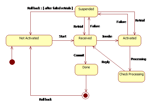
Figure 2.2.a Control behaviour of composite web service -State Diagram
In figure 2.2.a a filled circle is the initial state, hollow circle containing a smaller filled circle, indicates the final state, rounded rectangle, denotes a state which contains the name of the state and arrow, denotes the transition. The name of the
event causing this transition labels the arrow. A web services control and operational behavior has finites set of states and transitions. This is called as paths and is represented as follows. A path p( i→ j) in a web service W is a finites sequence of states and transitions starting at state si and ending at state sj , is denoted as p( i→ j) = {si→ si+1→si+2 … sj-1→ sj } for example in figure 2.2.a not activated → received → done is a path. In figure 2.2.a initially the state is in so = not activated state. When the request is received the process moves to received state. This state denotes the request is received from the user. In case of failure the system goes to suspended state which again goes back to not activated state after failure even after retrial state. Formally this can be represented as p(Received, failure)=Suspended if suspended is reached then the following transition takes place p(suspended ,retrial)=(received ˅ not activated) . If after retrial from the suspended state the received state is reached then the user can invoke any web service and get itself in activated state and the composite service system starts from here. The formal representation of this state can be represented as p(received, invoke) = (activated ˄ check processing ). From the check processing state the result is communicated back from the web service and thus the received state is again reached. Similarly other requests will then are invoked and go to the Activated state and then to check processing and again back to received state and after successful completion of all the requests the system goes to the done state which is the final state and from here the system again rolls back to the not activated state. The process of connecting operational and control behaviours together occurs by establishing correspondences between the respective states of these two behaviours. These correspondences implement the mapping step and result in forming conversation session.
Soundness and completeness with respect to operational and control aspects
Soundness in the formal methods says if φ1, φ2, . . . , φn ⊢ ψ is valid then φ1, φ2, . . . , φn ⊨ ψ is also valid. So in our example let W be a composite webservice and let C be the set of conversations in the operational behaviour and E be the set of conversations in control behaviour. Then W is sound if for all c belongs to C there exists e belongs to E such that c → e .
In formal language it can be written as {W= sound, ∀c ϵ C ∃e ϵ E : c → e } . Simillairly the completeness says that φ1, φ2, . . . , φn ⊨ ψ is valid then φ1, φ2, . . . , φn ⊢ ψ is also valid. In our example W is complete if for all e in E there exists c in C then e → c . In formal language it is written as {W=complete, ∀e ϵ E ∃c ϵ C : e → c }. Let us use the operational behaviour flow.
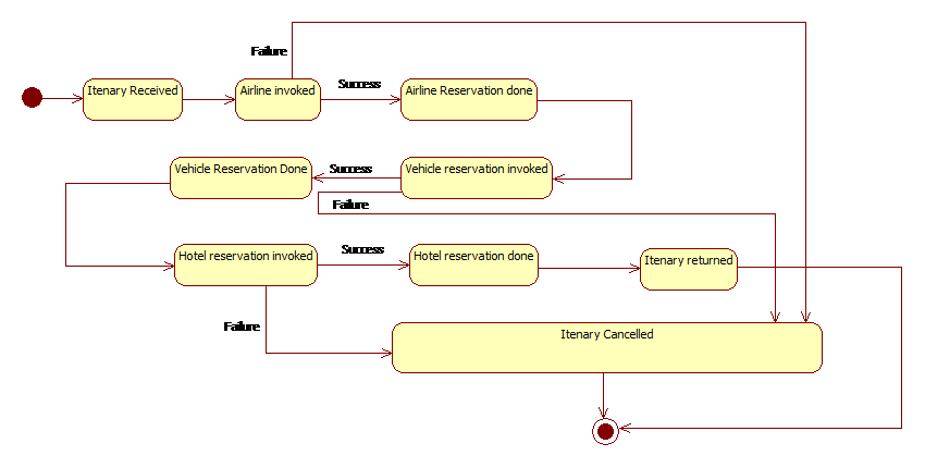
Fig 2.3.a Operational behaviour of ticket reservation system
In the operational behaviour first the system enters the Itinerary received after the itinerary is received the Airline invoked state is called and if it is success then it enters the Airline reservation is done and then the vehicle reservation is invoked. The hotel reservation is invoked vehicle reservation is done. If success the hotel reservation is done and the itinerary is returned and on failure of any three of the invoked state i.e. in Hotel reservation invoked, vehicle reservation invoked or in flight reservation invoked, the system goes to the Itinerary cancelled state and then the final state.
By considering the above operational behaviour from figure 2.3.a
In the operational behaviour first the system enters the Itinerary received after the itinerary is received the Airline invoked state is called and if it is success then it enters the Airline reservation is done and then the vehicle reservation is invoked. If success vehicle reservation is done and then the hotel reservation is invoked. If success the hotel reservation is done and the itinerary is returned and on failure of any three of the invoked state i.e. in Hotel reservation invoked, vehicle reservation invoked or in flight reservation invoked, the system goes to the Itenary cancelled state and then the final state. Conversation 1 =
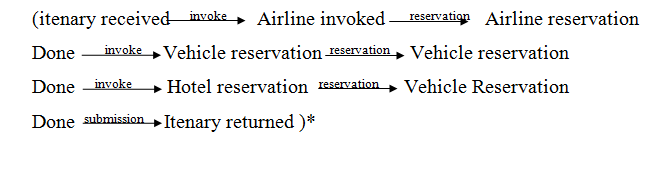
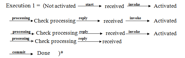
In the above example the Conversation 1 in the operational behaviour is mapped to the Execution 1 of the control behaviour and * means the loop. So since the conversation 1 maps to the valid execution, so we can say that the composition in figure 2.3.a is sound. Similarly the states not activated, received, activated, check processing, received and done in control behaviour of figure 2.2.a can be mapped to Itenary received, Airline invoked, Airline Reservation done of operational behaviour in figure 2.3.a .So since there exist a path in control behaviour of figure 2.2.a that can be mapped to the path in operational behaviour of figure 2.3.a ,we can say that the composition is complete.
Kripke structure of the system
A Kripke structure is used in model checking to represent system behaviour. In this structure the nodes represent the reachable states and edges represent state transitions. To structure the operational behaviour into Kripke model the following algorithm was used. Each state Sop in the operational behaviour was translated to a set of atomic states and transitions in the Kripke structure Mk. Each transition was translated to one or many transitions. If sop was an atomic state, then it translated into one state in Mk with the same content. Transitions between atomic states were translated to transitions between the corresponding states in the Kripke-like structure. As the model was simple so we had not bothered regarding the compound states or concurrent states. So for our operational behaviour the Kripke model looked as in figure 2.4.a
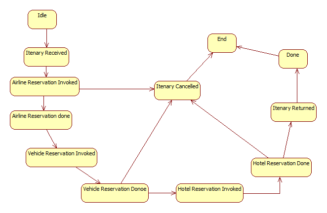
Figure 2.4.a Kripke model of operational behaviour
If we use Na for not activated state , Re for received state, A for activated state, Pr for processing state, Su for suspended state, Do for done and En for end then the above model can be converted using states as in figure 2.4.b using the above mentioned translation procedure.
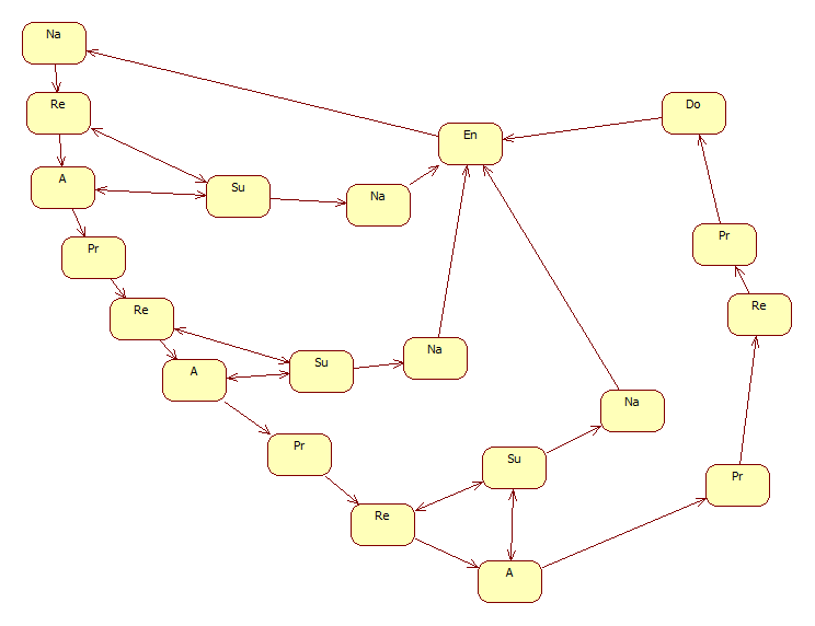
Figure 2.4.b Final Kripke model of composite web service
The Kripke model of figure 2.4.b is then reduced by using the reduction algorithm[1] to reduce the number of states and transition. The idea is that two states labelled with the same atomic propositions are equivalent and they can be reduced to only one state. For all s1 and s2 in the Kripke structure, if s2 is reduced to s1, then:
- If (s1, s2) and (s2, s1) are two transitions, then they are replaced by the transition (s1, s1).
- If only one of the two transitions exists, then it is removed.
- For all x, if (sx, s2) is a transition, then it is removed and replaced by the transition (sx, s1) if such a transition does not exist.
- For all y, if (s2, sy) is a transition, then it is removed and replaced by the transition (s1, sy) if such a transition does not exist.
By using the above algorithm the reduced Kripke model is shown in figure 2.4.c.
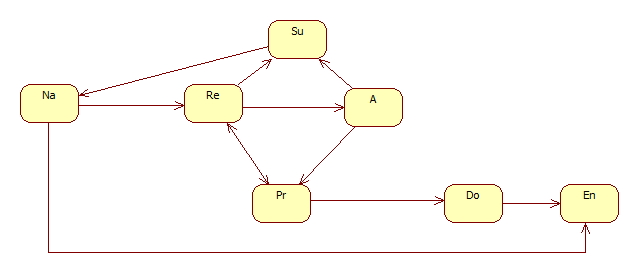
Figure 2.4.c Reduced Kripke model
Identification of formal specifications
To represent the logical properties the temporal logics such that linear temporal logic (LTL) and computation tree logic (CTL) is used to verify the properties of the system or model. The properties are associated with each state in the control behaviour. Before putting the specifications using Formal method symbols , first the specifications needs to be found out. So following are some of the specifications of the model.
- There exists always a received state or an end state after a not activated state.
- There is always a activated, processed, suspended, or done state after received state.
- There is a not activated and end state in future after a suspended state.
- There is always an end state in future after done state.
- There is always a not activated state in future after end state.
- There is a process or suspended state after activated state
- There is a done or suspended state on a path after received or processed state.
- There is always a path from state received to states activated, processed, suspended and done state.
- There is always a path to end state from done state
- There is always a path to received state or end state after not activated state.
- A path from received to next state suspended or from received to next state processed is always potentially reachable.
Click : For implementations and model checking of composite web services using NuSMV
References:
[1] Alicendra,C.et al.,”Formalization and Validation of Safety-Critical Requirements”,Creative Common Arts.
[2] Antti,J.,et al.,(1998)”Verification of Safety-Critical Systems: A Case Study Report on Using Modern Model Checking Tools”,1998,Dagasthul,Germany.
[3] Brown,D.,et al.,(2010)”Guidance for Using Formal Methods in a Certification Context”,May 2010.
[4] Decision and Information Analysis, Goizueta Business School(2001),”Model Checking – A Rigorous and Efficient Tool for E-Commerce Internal Control and Assurance”,17 September 2001,W.Wang,et al.
[5] Department of Computing, Imperial College London (2003),”Model-based Verification of Web Service Compositions”,2003,F.Howard,et al.
[6] Department of Computing, University of Surrey, Guildford, UK (2007),”An Automatic Test Case Generation Framework for Web Services”,3 september 2007,Z.Yongyan,Z.Jiong,K.Paul.
[7] Georgia, M.K.,et al.(2009)”Model-driven development of composite context-aware web applications”,27 March 2009,Software and Service Engineering Laboratory, Technological Education Institute of Piraeus, Dept. of Electronic Computing Systems, Petrou Ralli & Thivon 250, 12244 Athens, Greece
[8] Hoyt, L.,(2012)”Transitioning to RTCA DO-178C/DO-278A:A Business Manager Brief”,August 2012,Foliage
[9] Huth,M.,Ryan,M.,(2004)”LOGIC IN COMPUTER SCIENCE”,Second Edition,2004,Cambridge University Press
[10] Jamal,B.et al.,(2013)”Symbolic model checking composite Web services using operational and control behaviors”,2013,Concordia University.
[11] Laurent,P.et al.,”DO-178C/ED-12C versus DO-178B/ED-12B Changes and Improvements”,September 2012,ACG Solutions.
[12] Maddireddy,S.R.,”The Impact of RTCA DO-178C on Software Development”,Cognizant
[13] Melissa,K.(2009)”A formal verification approach of conversations in composite web”,August 2009,Concordia University
[14] NASA Ames Research Center, Moffett Field, CA 94035, USA (2010),”Linear Temporal Logic Symbolic Model Checking”,29 June 2010,Y.R.Kristin.
[15] Raman,K.,et al.(2006)”Verification and Validation of Web Service Compositions “,27 June 2006,DIT, University of Trento, Italy.
[16]Roberto,C. et al.“NuSMV 2.5 Tutorial”, First Edition, FBK publisher
[17] School of Computing,University of Utah ,”Model Checking Web Services”,Shrigondekar,Amit.,De Silva,L.,Thulasinathan,A.
[18] Stephen A.J.,”Certification of Safety-Critical Software Under DO-178C and DO-278A”,NASA Ames Research Center, Moffett Field, CA, 94035
[19] Wlad,J.,(2012)”Architectural Trends in Avionics Systems: Multi-core and DO-178C”,April 2012,Aerospace and Defense FAA DER Systems and Software.
[20] Xian,F.(2004)”Formal Specification and Verification of Asynchronously Communicating Web Services”,September 2004,UNIVERSITY of CALIFORNIA.
[21]Yanick,M. et al.(2013) “Testing or Formal Verification: DO-178C Alternatives
and Industrial Experience”,2013,IEEE computer society
[22] Zoltan,T.H.(2007)”Model Checking – A Rigorous and Efficient Tool for Preventing E-business Failures”,August 2007,THE UNIVERSITY OF TEXAS AT AUSTIN
[23] 21st International Joint Conference on Artificial Intelligence (IJCAI)(2009),”Behavioral Description Based Web Service Composition Using Abstraction and refinement”,2009,H.Kil,et al.
